laser_driver
所属分类:能源行业(电力石油煤炭)
开发工具:Others
文件大小:0KB
下载次数:2
上传日期:2018-10-01 19:59:58
上 传 者:
sh-1993
说明: 节能恒流二极管激光器驱动器,
(Energy efficient constant current diode laser driver,)
文件列表:
eagle_files/ (0, 2018-10-01)
eagle_files/OKR-T-50-W12-C.lbr (8639, 2018-10-01)
eagle_files/REDCUBE.lbr (7713, 2018-10-01)
eagle_files/laser_driver.brd (333928, 2018-10-01)
eagle_files/laser_driver.sch (1117821, 2018-10-01)
images/ (0, 2018-10-01)
images/sch.png (52194, 2018-10-01)
images/slope.png (1154398, 2018-10-01)
# laser_driver
Energy efficient constant current diode laser driver for CW operation
# Specs
* Input voltage range: 6.5V to 13.8V
* Output voltage range: 0.6V to 2.5V
* Max Output current: 40A to 50A
* Energy efficiency: Around 90% @ Iout > 10A
* Analog input voltage or >500 Hz PWM
* Operating ambient temperature: up to +70°C
* No overshoot
* Protected against reverse-polarity, short-circuit, over-voltage and over-temperature
# Schematic & description
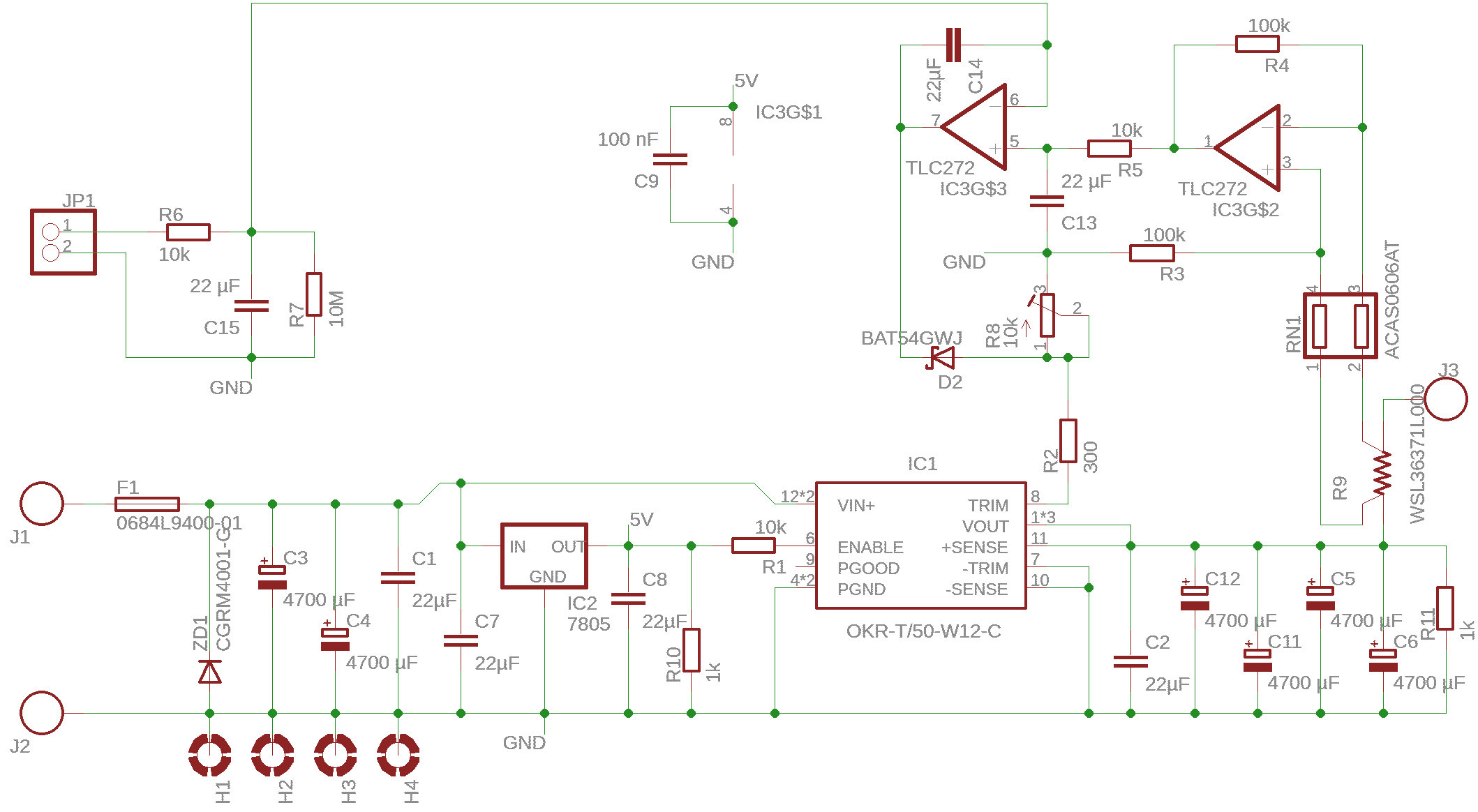
An analog control voltage with 1V/10A or a 5V 500 Hz PWM signal with duty cycle 20%/10A is applied to JP1 and smoothed in a low-pass filter. IC3G$2 is a current shunt amplifier, generating 1V/10A. IC3G$2 compares the input control voltage and the actual output current voltage and drives the DC-DC converters trim pin accordingly. The circuit is an artifically slowed closed control loop because CW laser diodes often cannot take steep current slopes.
# Slope measurement
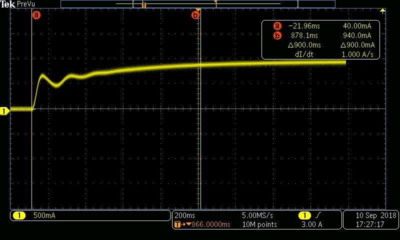
The displayed schematic is very slow, but guaranteed to never overshoot or oscillate. If desired for capacitors C13 and C14 lower values can be used to make the control loop respond faster. The displayed current waveform shows a start from 0A to 10A. It gets less wiggly when the baseline voltage is set closer to the laser diodes forward voltage, or when the current is not turned off all the way to 0A.
# Baseline Vout setting
Short or connect 0V to JP1, do not leave floating. Measure output voltage and adjust potentiometer R8 to set the baseline Vout to just under forward voltage of your laser diode. Don't make this adjustment while the laser diode is connected, there's a good chance of destroying it.
近期下载者:
相关文件:
收藏者: